When working in a Detail View, there will be times Fill Patterms are required to be removed:
Monday, September 8, 2008


Thursday, May 15, 2008
Sloped Beams: How to Specify Workplanes for Beam Systems
Most firms to not work with standard square building with simple horizontal beams throughout. There will definitely be times where all structural firms will need to place Beam Systems on an angle...but this is not as easy as the 1-click procedure used to place Beam Systems on bays created with horizontal bracing. This will need to be done in sketch mode, but there is a step necessary prior to sketching the Beam System to make sure the Beam System is following the slope of the boundaries of the Bay. The structural user needs to specify the sloped Bracing as the Workplane:
1) Below is an Elevation View of my structure:

2) Select the Workplane button on the top right hand corner of your Toolbars:

3) A dialog box will pop up to ask where you want to place your new Workplane. Select to Pick A Plan:

4) Select the top of the Beam you want the Beam System to follow. First I selected the taller structure. I will need to select the two portions of the structure seperately:

5) A dialog box will pop up to ask what View you want to work in. Select the View (I selected the Level 3 Floorplan), and it will immediately open the View:


6) A dialog box will pop up to notify you that you cannot use the 1-click creation to create the Beam System.
.png)
7) You will directly enter Sketch Mode. Sketch out the Beam System as you normally would:


Note: The Beam System follows the Beam you selected as it's Workplane...
Tuesday, April 29, 2008
Back to Basics
Many of you may already know this, but I have been asked this questions several times, and I thought I would address it:
What is the difference between Auto-Detect or Inch when importing in an AutoCAD file?
The difference is that you may have actually selected a different scale in the AutoCAD drawing other than the default inch. Many users will change the drawing to metric, feet, or a different type of scale all together.
Sometimes we just need to go Back to the Basics :-)
Friday, April 18, 2008
Tech Camp 2008 - Revit Structure Extensions
Well, now that the new versions of the Autodesk projects have been released and sent out to clients, I am going to stop posting the new features. If you are still interested in viewing the new features of any of the Autodesk products, please view the New Features Videos on my company's Website at www.masterg.com.
I would like to, instead, reflect on most productive session I took at Tech Camp 2008, Revit Structure 2009. We discussed the new story for the structural industry. Now, with the release of Revit Structure Suite 2009, AutoCAD Structure Detailing 2009 is included, providing Steel and reinforced concrete detailing and shop drawings, as well as state-of-the-art formwork drawings. At this time, it is only available in Metric, but it the begining of completing the story for the structural engineering industry.
Also, we discussed the Extensions for Revit Structure 2009, now available on www.extensions4revit.com. They are free to all Revit Structure users on Subscription. When you select to dowload the Extensions, you will be redirected to the Autodesk Subscription site. Make sure you have your Subscription information nearby, if you are logging on for the first time. Below are the additional functions you will benefit from after downloading the Extensions Manager:
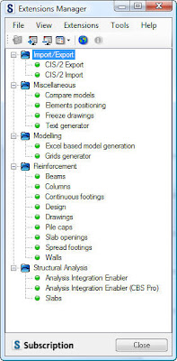
Import/Export CIS/2
1) Import CIS/2: This application allows Revit Structure users to Import files created in other applications in the CIS/2 format.
2) Export CIS/2: This application allows Revit Structure users to export files to other applications in the CIS/2 format.
Miscelaneous
1) Compare Models: Extension provide a functionality of comparing two projects defined in Revit products. The comparison results will be provided in a form of an htmp report and differences between projects will be highlighted.
2) Elements Positioning: This module creates position labels for selected elements in a Revit Structure project.
The extension allows for:
-Collecting elements and dividing them into categories and types
-Sorting elements depending on their vertical and horizontal locations in projects
-Inserting a Mark parameter string with a user-specified position formula
-Adding tags that display the value of the Mark parameter on views selected by the user
3) Freeze Drawings: The Freeze Drawings Extension provides facilities for the user to unlink the drawing from the object model, so the drawing will remain unchanged despite any changes in the Revit® Structure model.
4) Text Generator: This extension enables the automatic generation of text notes in Revit Structure. The generation process is based on text inserted into the extension (from a file or directly from the keyboard) and settings defined by the user. The text can be divided according to separators or maximum size. The arrangement of newly created text notes is based on a table scheme. In addition, documents saved in Microsoft® Word format may be read directly.
Modeling
1) Excel Based Model Generation: This application enables user defined MS® Excel data to automatically define the geometry of a structure in Revit® Structure. The Extension generates beams, columns, levels, walls and footings.
2) Grids Generator: The Extension provides a “wizard” that enables the definition and generation of axes grids and levels in Revit projects. This Extension also provides facilities to automatically generate columns, beams, walls and footings on grid intersections.
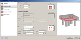
Reinforcement
1) Beams: The beam “extension” provides powerful facilities to define both simple and complex reinforcement patterns for RC beams. The module creates true 3D “intelligent” rebar data in Revit® Structure. This Extension allows the user to define single span beams of rectangular cross section and incorporates multi span definition and additional cross section shapes.
2) Columns: The column “extension” provides powerful facilities to define both simple and complex reinforcement patterns for RC beams. The module creates true 3D “intelligent” rebar data in Revit® Structure. This Extension allows the user to define columns of various cross section types.
3) Continuous Footings: The Extension provides powerful facilities to define reinforcement patterns for continuous footings. The module creates 3D “intelligent” rebar data in Revit Structure. This Extension allows the user to define reinforcement for various footing types, including curved footings.
4) Design: The Extension allows performing one of the following processes:
-Verification of reinforcement defined in Revit® Structure for a selected RC structure element; verification is performed in ROBOT Millennium in compliance with the requirements of an RC code selected by the user
-NOTE: verification of reinforcement in ROBOT Millennium is possible only for the reinforcement generated using a dedicated Revit® Structure Extension (Reinforcement of beams, Reinforcement of columns, etc.); verification of reinforcement which is drawn by means of options available in Revit® Structure is impossible
-Design (generation) of reinforcement in ROBOT Millennium for an RC structure element selected in Revit® Structure; reinforcement is calculated and generated in ROBOT Millennium in compliance with the requirements of an RC code selected by the user
-Import of reinforcement generated in ROBOT Millennium to Revit® Structure
The Extension enables design / verification of reinforcement both for stand-alone elements and for objects being components of a larger structure model.
In the current program version reinforcement can be verified / calculated for the following types of structure model elements:
-RC beams
-RC columns
5) Drawing Enabler: The Extension allows the user to generate 2D production drawings of typical reinforced concrete components.
The RC details are made with respect to a variety of national and code dependent regulations, with additional support for Imperial units available later in the year. The drawings are processed by Robobat’s AutoCAD application RCAD Reinforcement or imported into Revit Structure in the form of a DWG file.
6) Pile Caps: The Reinforcement of pile caps extension provides powerful facilities to define reinforcement patterns for pile caps. The module creates 3D “intelligent” rebar data in Revit Structure. This Extension allows the user to define reinforcement for a pile cap of various cross section shapes.
7) Slab Openings: The Reinforcement of slab openings extension provides powerful facilities to define reinforcement patterns for openings in slabs. The module creates 3D “intelligent” rebar data in Revit Structure.
This Extension allows the user to define reinforcement for rectangular openings definied within a concrete slab and also incorporates additional opening positions, circular shapes and additional rebar configurations.
8) Spread Footings: The Reinforcement of spread footings extension provides powerful facilities to define reinforcement patterns for spread footings. The module creates 3D “intelligent” rebar data in Revit Structure. This Extension allows the user to define reinforcement for various footing types and column cross section shapes.
Structural Analysis
1) Analysis Integration Enabler: The “enabler” facilitates the powerful bi-directional integration of Revit® Structure and ROBOT Millennium. Upon installation of the enabler, the user can dynamically import and export data between the two products.
2) Analysis Integration Enabler (CBS Pro): The “Enabler” facilitates the powerful bi-directional integration of Revit Structure and CBS Pro functionality. Upon installation of the Enabler, you can dynamically import and export data between the two products.
3) Static Analysis of Slabs: The Static analysis of slabs extension allows performing static analysis of a slab defined in a Revit Structure model.
It enables loading necessary information from Revit Structure such as: slab geometry, constraints/supports, load cases, load combinations, loads. Results obtained for a defined slab model are displayed in the graphical (maps of a selected quantity) and tabular form.
Additionally, obtained results with data concerning the analyzed slab may be presented in the form of a report (in the HTML format); a report for a slab can be printed, saved to a file or sent to a MS Excel© or MS Word© document.
Similarly to begining the implementation of Revit Structure itself, it is not necesary to begin using all of the features of the Extension Manager at once. Begin with just one, such as freezing a drawing. Work with it. Perfect the procedure. Then slowely add another functionality. It is all about improving your business practices.
Thursday, April 10, 2008
New Features in Revit Structure 2009 - Beam Tag Improvements
Beam tagging is an important part of creating a structural framing plan. Depending on the complexity of the structure, beam tags can contain many different pieces of information. Providing the structural engineer and drafter with the tools to place and modify this information is crucial.

Spot elevations are improved to enable you to select beams in Coarse mode. The spot elevation “asks” the beam for its elevations at the end- and midpoints, based on its bounding box. Note that spot elevations can be taken at the top or bottom of beams. Spot dimensions (spot elevations and spot coordinates) can also now be rotated.

Wednesday, April 9, 2008
New Features of Revit Structure 2009 - Dimensioning Enhancement
Well, finally, we have the ability to override text in a dimension. Now, you cannot change a dimension to another dimension, but you do have the ability to remove the dimension itself and replace it with text.


You also have the ability to add a Prefix or Suffix, as well as add text above or below the dimension line, making detailing much more flexible!


Friday, April 4, 2008
New Features of Revit Structure 2009 - Dimensioning Enhancement
Two new Dimension Threads have been added for the ability of dinensioning your Elements: Baseline and Ordinate. This will bring up the total number of options to 3 (including the original Continuous Dimension Thread)

First, the original Continuous Thread is still available, as always:

Secondly, the Baseline Thread option is now available:

Lastly, the Ordinate Thread is also available:

Thursday, April 3, 2008
New Features of Revit Structure 2009 - Dimension Improvements
Revit Structure 2009 has improved many aspects of the Dimensioning tool.
You can now:
You can now:
Dimension at line intersections: lines, grids, reference planes, location lines (walls, floors)

Run linear dimensions to center of arcs without turning on visibility of the center mark and dimension concentric arcs with linear dimensions
Apply bold, italic, underlining, and width factor to all dimension styles
Tuesday, April 1, 2008
New Features of Revit Structure 2009 - Foundation Improvements
At long last, users can now add multiple Footings and Wall Foundations at the same time, as well as manipulate (strecth) Wall Foundations past the Wall they are connected to:

Similar to adding Columns and Beams, users can now use Grid Intersections to add Footings. Now, however, they can also use Columns to add Footings.

When placing Wall Footings, there is now an addition to the Option Toolbar where users can select to add multiple Wall Footings to a multiple selection of Walls at the same time.

Lastly, users can stretch Wall Footings beyond the Walls they are attached to. Now use the grips at each end of the Wall Footing to manually stretch the Element.
Monday, March 31, 2008
New Features of Revit Structure 2009 - Concrete Reinforcement (Rebar Covers)
The Rebar Cover is now a property of concrete elements, making it much more flexible to edit and modify. Covers can be set by the different faces of the concrete element, enabling you to take into account the exposure of certain faces to weather.

A new Rebar visibility state, also enables you to view Rebars as solid in the 3D View.


A new Rebar visibility state, also enables you to view Rebars as solid in the 3D View.


New Features of Revit Structure 2009 - Concrete Reinforcement
Revit Structure 2009 increases the user’s ability to place individual reinforcement bars into a concrete model as specified by third-party analysis and design software.
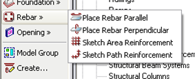
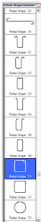
Many standard rebar shapes (00, 01, S1, T1, and so on, for ACI codes) are available in a browser, and each bar can be placed with one mouse-click.
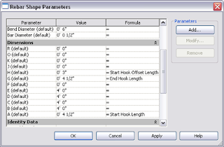
Rebar shape dimensions (A, B, C, D, E) can be edited in a manner similar to that for the Revit families.
Additional parameters can be displayed in schedules, and reinforcement automatically created by a third-party application can be accurately scheduled.

Sunday, March 30, 2008
Release Dates of Revit 2009 Software!
Well, finally, the shipment dates of the Revit Software is out! Get ready for April 15th!
Revit® Architecture
April 15
AutoCAD® Revit® MEP Suite
April 15
Revit® Structure
April 15
Revit® Architecture
April 15
AutoCAD® Revit® MEP Suite
April 15
Revit® Structure
April 15
Thursday, March 27, 2008
New Features of Revit Structure 2009 - Available Extensions
Autodesk® Subscription customers can benefit from extensions available for Revit Structure 2009.
The Reinforcement extensions increase the user’s ability to incorporate automatic reinforcement into concrete elements.

Easy to install and use, they extend the capability of Revit Structure 2009 to handle concrete reinforcement details.

As shown, reinforcement macros are avilable for concrete columns, beams, footings, walls, pile caps, and slab openings.

Wednesday, March 26, 2008
New Features of Revit Structure 2009 - Vertical Move by Common Join
In previous releases, the ability to change the elevation of Beam Joins was only available for individually selected Beams. Now, in Revit Structure 2009, the elevation control is possible for several Beams joined at one intersection.
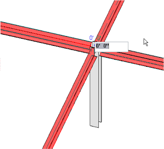
The user can now select a set of Beams at a common join and change the elevation. When an elevation is changed using the control, the selected beams disjoin, move to the desired location, and rejoin. In each beam property, the end and start level offset values are adjusted correspondingly.

The user can now select a set of Beams at a common join and change the elevation. When an elevation is changed using the control, the selected beams disjoin, move to the desired location, and rejoin. In each beam property, the end and start level offset values are adjusted correspondingly.

Friday, March 21, 2008
New Features of Revit Structure 2009 - Edit Beam Joins
In Revit Structure 2008, cutbacks were applied to all members of an end join, no matter what. They were all the same in the Settings Pull Down Menu, specific to the elements they were joined to. However, now it Revit Structure 2009, we are allowed to change the join at each end of Beams, depending on the need:
Imagine viewing your joint this way:

How about this way?

What about this?

The beauty is that this can occur in a singe model with several different connections, different areas of the model, dofferent beams...Note that the shape handles at the end of the beams remain. These shape handles were created for the Coping tool; therefore complete coordination between the symbolic (Coarse mode) and model geometry (Medium and Fine modes) cannot be guaranteed with the use of the shape handles. These options are available for wood, steel, as well as concrete.
Wednesday, March 19, 2008
New Features of Revit Structure 2009 - Slope Slabs
The first enhancement of Revit Structure 2009 allows you to edit the shape of Slabs with curved edges: 


Improvements have also been made when adding points to a Slab. Now, users have the ability to manipulate the split lines that are added to the Slab when the point is positioned:

Lastly, the option does not limit the actions to Concrete Slab. Now, Slabs made of Metals Decks can also be sloped and warped:

Tuesday, March 18, 2008
New Features of Revit Structure 2009
Structural Modeling
Sloped Slab Shape Edit
- Edit the Shape of Slabs with Curved Edges
- Modify the Split Lines that the Software automatically creats in the Slab when it is warped
- Slabs made of Metal Decks can now also be sloped and warped
Beam Cutbacks
- Modify the Join Configuration and provide Graphical Controls at the end of the Beams participating in a Join
- Miter Joins can be created for Elements of the same Type
Vertical Move by Common Join
- Elevation Control at the intersection of several Elements that Join
Avaialble Extensions
- Reinforcement Macros for Concrete Columns, Beams, Footings, Walls, Pile Caps, and Slab Openings
Concrete Reinforcement
- Place individual Reinforcement Bars into a Concrete Model
- Many standard Rebar Shapes are available in a Browers
- Rebar Shape dimensions can be edited in a manner similar to Revit Families
- Additional Parameters can be displayed in Schedules
- Reinforcement automatically created by a Third-party Application can be accurately scheduled
- Covers are now a Property of Concerete Elements
- View Rebars as Solid
Foundation Improvements
- Create multiple Foundations at the same time
- Wall Foundation Ends can now be Modified
Construction Documents
Dimension Improvements
- Dimension to Intersections
- Run Linear Dimensions to Center of Arcs without turning on Visibility of the Center Mark
- Dimension Cencentric Arcs with Linear Dimensions
- Apply Bold, Italic, Underlining and Width Factors to all Dimension Styles
- Create a set of Dimensions that all start from a common Baseline
- Create multiple Dimensions that measure a perpendicular disctance from an Origin Point
Dimension Text Override
- Replace Numerical Values with Text Values
- Add Supplemental Text to a Dimension String
Beam Tag Improvements
- Place Spot Elevations on Beams at the Top or Bottom
- Place multiple Beam Tags
- Tag Curve-Driven Elements
- Create a Single Label from multiple Parameters
Concrete Drawings
- Concrete Auto-Join: Column to Slab, Column to Wall, Beam to Slab, Beam to Wall, Slab Edge to Slab
- Enhanced Default Join of Beam to Beam
Graphical Column Schedule
- Add shifted Columns to Graphical Column Schedules
- Add Grouped Columns to Graphical Column Schedules
- Add a drop-down list to the Column Element Properties that shows different Graphical Column Schedule Label Combinations
Revision Numbering
- Revision Tags and Schedules can use Alphabetical, Alphanumeric or Mixed Convensions
- New Revision Parameters have been created for Title Blocks
- New Revision Columns have been created
- Add Revision Names without a Cloud
Usibility
Selection Count
- Count the Number of Objects in different Categories within the Filter Dialog Box
Visibility Tools
- Visibility Graphics for Revit links available "By Linked View" for Sections, Elevations and 3D Views
- Improved Linework for linked files
3D Navigation
- View Cube Feature
- Steering Wheel Feature
Linked Files Visibility
- Native DWF support for Windows Vista users
- No Plug-Ins required
- Windows XP support available
Wednesday, March 12, 2008
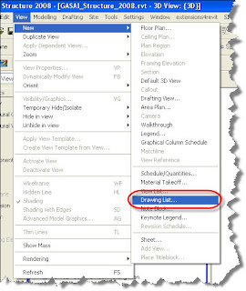
Using Drawing List to Speed Up Productivity
In larger firms, it is most likely that multiple people will be working in the same file, and creating separate sheets, needing the Checked By, Drawn By, and Approved By to have a different set of initials. However, in smaller firms, one designer may be working on creating all the sheets, working on all the plans, sections, details, etc. This can make for a very timely process when this information needs to be entered in for every sheet, everytime a new sheet is created. However, utilizing the Drawing List, even if not in the actual final set of Construction Documents, may com in handy here:
First, create a new Drawing List:
First, create a new Drawing List:

Second, add the necessary Fields/Parameters, as if you were creating a schedule:
Lastly, change the necessary information in the Drawing List, rather than in each individual Sheet…
Subscribe to:
Posts (Atom)
My Blog List
-
-
Topography Background Process - Can't Save5 months ago
-
-
BIM and Beam blog has been moved10 years ago
-
-
-
Introducing Autodesk Insight 36010 years ago
-
Turning the Page11 years ago
-
-
I've MOVED14 years ago
-
-
Revit Inside - Architecture19 years ago
-